Flight Simulator
By Lucas Li
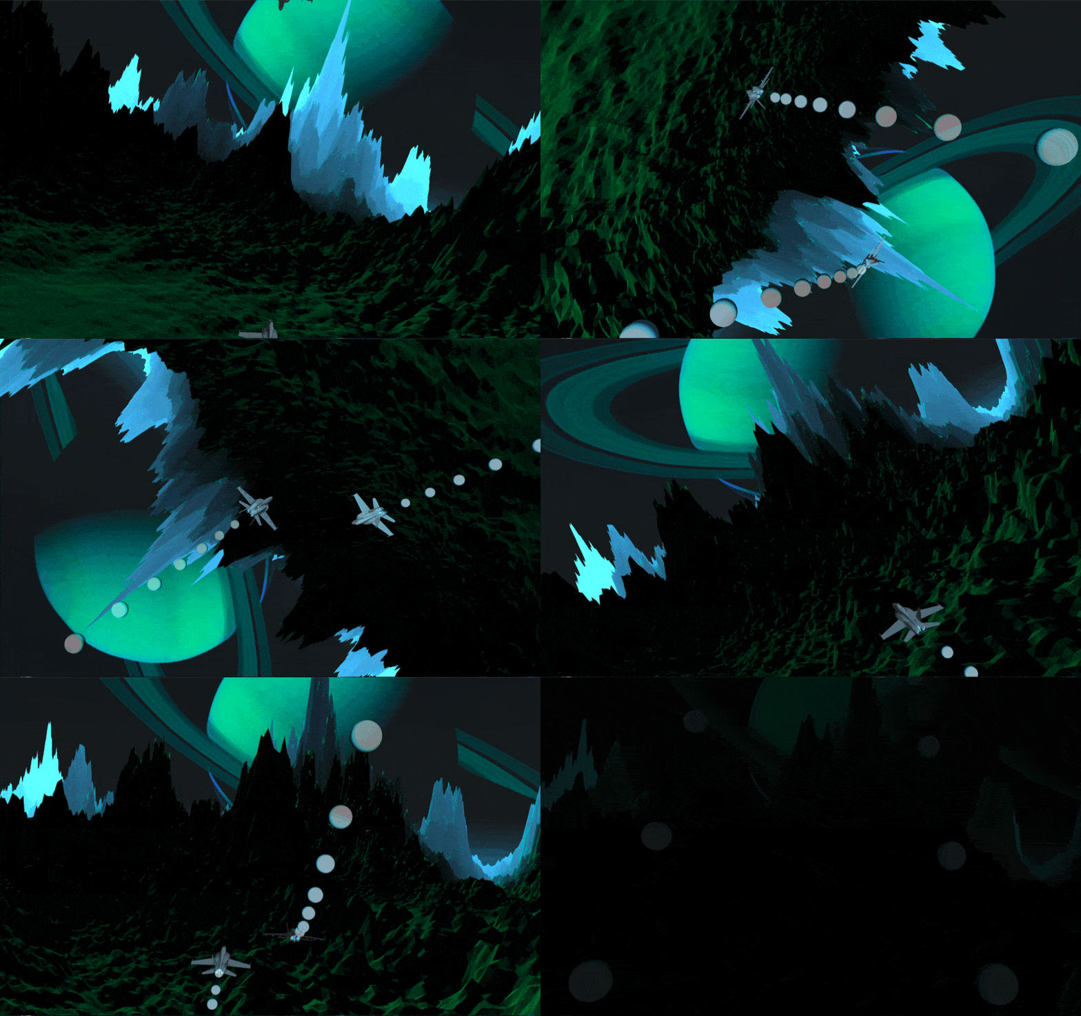
The Flight Simulator program involves creating an action-packed scene with flying planes, dynamic camera movements, and procedural generated terrain.

The project’s goal is to exhibit OpenGL’s math library GLM to practice the uses of quaternions and interpolations. The key focus is on setting up curved flight paths using quaternions & splines, ensuring accurate plane rotations, and incorporating various maneuvers like barrel rolls and screws.
Overview
The project is a software development project that uses modern technologies and frameworks to create a graphics-intensive application.
- C++11 as the main language
- Modern OpenGL/GLSL as the graphics API
- GLEW for cross-platform initialization of OpenGL
- GLFW for windowing
- Eigen for linear algebra
Assets
Besides using a plane.OBJ file, the following height map is used as the base of the terrain:
- Height map

Implementation
The main goal of this project is to use Quaternions and Interpolations to create pathways for the planes and camera. I’ve also included some intriguing features like Procedural Generated Terrain and Terrain Deformation that syncs with the beat of the background music.
Quaternions & Interpolations

The motion of the planes can be categorized into two key aspects: position and rotation.
Position
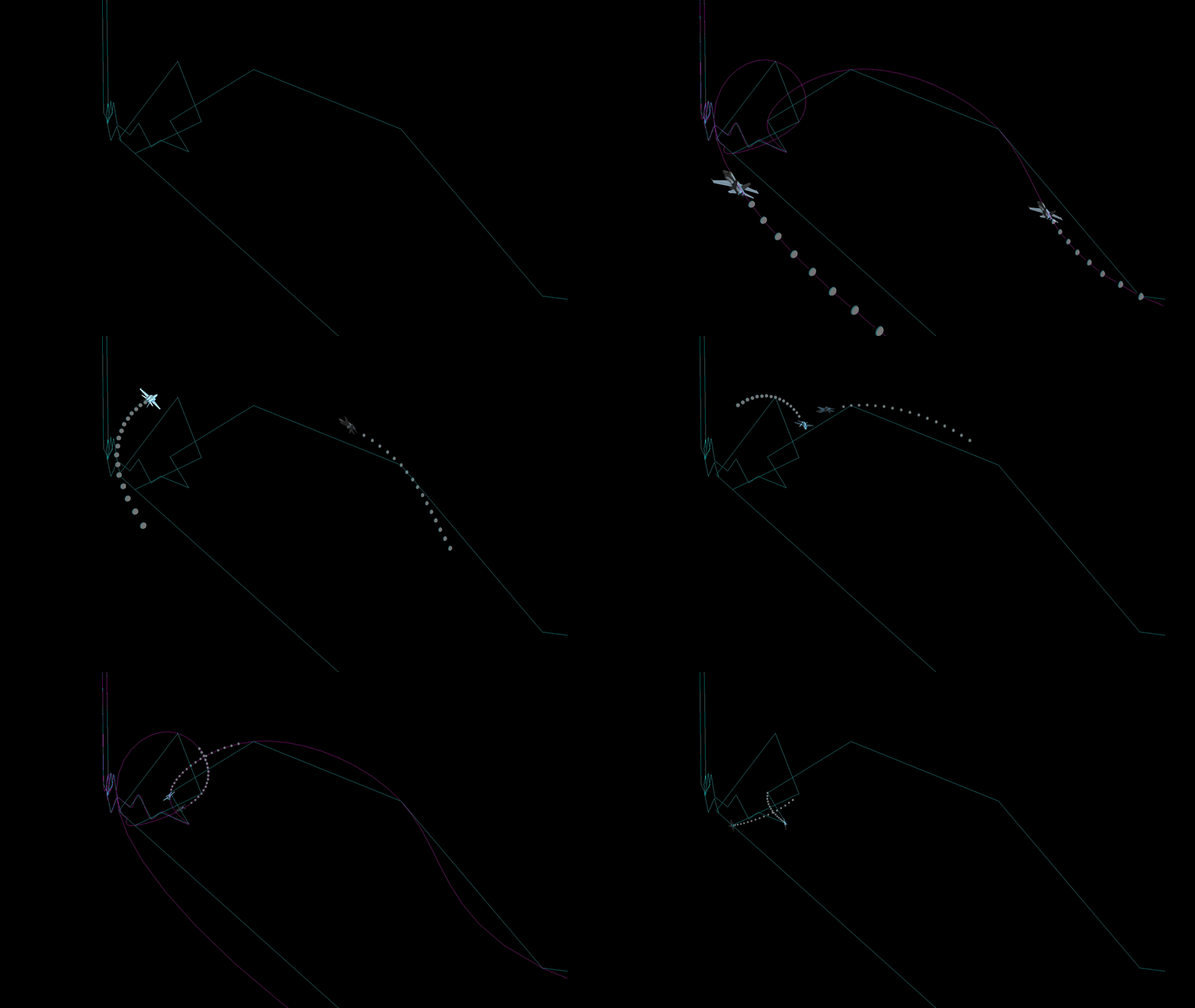
The position of each plane is initially set using an array of points (forming in blue), which are then utilized to create a spline (forming in purple).
line_1.push_back(vec3(3.0f, 26.0f, 10.0f));
line_1.push_back(vec3(3.0f, 24.0f, 0.0f));
line_1.push_back(vec3(3.0f, 20.0f, -20.0f));
line_1.push_back(vec3(7.0f, 24.0f, -35.0f));
While the planes can move more smoothly along the splines, the resulting motion may still appear jagged without interpolation between the points. Here is a simplified version of the position interpolation using linear interpolation between consecutive points on a path:
Since our planes always are between 2 points in the array, we need to figure out the current 2 points that the planes are in at current frame time.
Calculate the distances between consecutive points and the total distance traveled is always better then using the number of points directly to avoid undesired change in speed due to the difference in distances between points:
for (int i = 0; i < points.size() - 1; i++) {
    distances[i] = glm::distance(points[i], points[i+1]);
    total_distance += distances[i];
}
Then, we can calculate the constant speed of the plane:
float speed = total_distance/total_time;
To find the 2 points with the corresponding interpolation factor, here is my approach:
// 1. Calculate the current distance from the start point (points[0])
float distance_from_start = curTime * speed;
// 2. Find the current index (cur_index) of the segment on the path:
int cur_index = 0;
while (cur_index < points.size() - 2 &&
        distance_from_start > distances[cur_index])
{
    /* keep decrement the distance from the passed points to get to
       the distance from the current point to the next point */
    distance_from_start -= distances[cur_index];
    cur_index ++;
}
cur_point = cur_index;

// 3. Calculate the interpolation factor (interp_factor) based on the distance variable:
float interp_factor = distance_from_start / distances[cur_index];
Lastly, interpolate the position using mix() (interpolation function in GLM):
vec3 p1 = points[cur_index];
vec3 p2 = points[cur_index+1];
return mix(p1,p2,interp_factor);
Rotation

The plane’s rotation is partially controlled (yaw & pitch) by the path it takes, as the forward vector aligns with the direction to the next point. However, the planes’ roll is controlled programmatically in order to perform certain actions and replicate accurate rotation motions.
Similar to the positions, the rotations are also being stored in an array, but only the z axis (roll) rotation in degrees:
z_rot_1.push_back(0.0f);
z_rot_1.push_back(20.0f);
z_rot_1.push_back(40.0f);
z_rot_1.push_back(20.0f);
For interpolation, we calculated the current index and next index based on the ratio of the current time to the total time:
// ratio calculation
float ratio = curTime/total_time;
// find the current index and next index
int i1 = (int) (ratio * (z_rot_1.size() - 1));
int i2 = i1 + 1;
// edge case handling
if (i2 >= z_rot_1.size()) i2 = static_cast<int>(z_rot_1.size()) - 1;
// find the rotations based on indices
float ez1 = z_rot_1[i1];
float ez2 = z_rot_1[i2];
Next, we find the interpolation factor using a similar approach, but with fixed unit:
float unit_time = total_time/(z_rot_1.size()-1);
float cur_ratio = curTime - (unit_time * i1);
float rot_factor = cos_interp_float(cur_ratio / unit_time);
Instead of using linear interpolation, I wrote my own cosine interpolation for the rotation to achieve better animation between 2 rotation degrees.
float cos_interp_float(float t)
{
    return 1.0f - (cos(t * 3.1415926)+ 1.0f) / 2.0f;
}
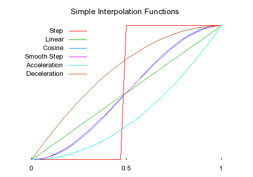
As a side note, there are many different ways to interpolate between animations, and some of the approaches are non-linear.

The curve starts slowly, accelerates in the middle, and then slows down again as it approaches the end point. This curve is created using the cosine function, which provides a smooth transition with a gradual change in rate.
To calculate the yaw & pitch of the planes, we need to find the forward vector using cosine interpolation again:
// determine the three points needed for the rotation interpolation
vec3 p0 = points[cur_index-1];
vec3 p1 = points[cur_index];
vec3 p2 = points[cur_index+1];
// set the up vector to be align with the y axis for now
vec3 up = vec3(0,1,0);
// find the unit vectors for forward directions
vec3 direction0 = normalize(p1-p0);
vec3 direction = normalize(p2-p1);
// interpolate between 2 vectors to find the forward vector
vec3 forward = cos_interp(rot_factor, direction0, direction);
// calculate the right vector
vec3 ex = cross(forward, up);
// recalculate the up vector
vec3 new_up = cross(forward, ex);
The up vector is first initialized to (0, 1, 0) in the following code, reflecting the positive y-axis direction. However, as the item rotates along its journey, the forward direction changes, resulting in a change in the orientation of the object’s local coordinate system. As a result, in order to keep the rotation matrix orthogonal and orthonormal, the up vector must be computed based on the new forward direction.
Form the rotation matrix:
mat3 rotation_matrix(ex, new_up, forward);
Since the rotation between states can be dramatic for a plane, using quaternions interpolation can avoid Gimbal lock for unexpected behaviors:
// Create a 4x4 matrix for quaternion convertion
glm::mat4 matrix;
matrix[0] = glm::vec4(rotation_matrix[0], 0.0f);
matrix[1] = glm::vec4(rotation_matrix[1], 0.0f);
matrix[2] = glm::vec4(rotation_matrix[2], 0.0f);
matrix[3] = glm::vec4(0.0f, 0.0f, 0.0f, 1.0f);
// convert matrix to quaternion
quat q = quat_cast(matrix);
// interpolate the roll of the plane then apply to the forward vector
q = angleAxis(radians(mix(ey1,ey2,rot_factor)), forward) * q;
// convert back to 4x4 matrix for GLM function calls
rot = mat4_cast(q);
Procedural Generation
The terrain is generated using a 1000x1000 mesh, incorporating a texture Vertex Buffer Object (VBO). The texture VBO utilizes the height map image previously displayed as the base height reference for the terrain. Additionally, a noise function is employed to control the variation and intricacies of the terrain details.
Noise
The noise implementation consists of multiple layers, starting with a basic hash function utilized for randomization purposes.
float hash(float n)
{
    return fract(sin(n) * 753.5453123);
}
Next, the snoise function is created as an implementation of a 3D simplex noise function, which generates pseudo-random values based on the input vector x. It is used as a building block for creating more complex noise function.
float snoise(vec3 x)
{
    // integer part
    vec3 p = floor(x);
    // fractional part
    vec3 f = fract(x);
    // smooth interpolation
    f = f * f * (3.0 - 2.0 * f);

    /* mix and interpolate the hash values based
    on the fractional values f in each dimension */
    float n = p.x + p.y * 157.0 + 113.0 * p.z;
    return mix(mix(mix(hash(n + 0.0), hash(n + 1.0), f.x),
        mix(hash(n + 157.0), hash(n + 158.0), f.x), f.y),
        mix(mix(hash(n + 113.0), hash(n + 114.0), f.x),
            mix(hash(n + 270.0), hash(n + 271.0), f.x), f.y), f.z);
}
The final layer is the noise function. The noise function combines multiple levels of noise values with different frequencies and amplitudes.
float noise(vec3 position, int octaves, float frequency, float persistence)
{
    /*
        octaves: level of details,
                accumulates the noise values at each octave
        frequency: controls how fast the noise changes
        persistence: controls the amplitude reduction at each octave
    */
	float total = 0.0;
	float maxAmplitude = 0.0;
	float amplitude = 1.0;
	for (int i = 0; i < octaves; i++) {
		total += snoise(position * frequency) * amplitude;
		frequency *= 2.0;
		maxAmplitude += amplitude;
		amplitude *= persistence;
		}
	return total / maxAmplitude;
}
By adjusting the parameters octaves, frequency, and persistence, we can create different variations and complexities of noise landscapes.
Lastly, applying this function twice to produce even smoother result.
// base noise
float height = noise(tpos.xzy*3, 11, 0.03, 0.6);
// adjustment noise function
float adjustment = noise(tpos.xzy*3, 4, 0.004, 0.3);
// power amplification on the second noise
adjustment = pow(adjustment, 5)*3;
// noise mixing
height = adjustment*height;
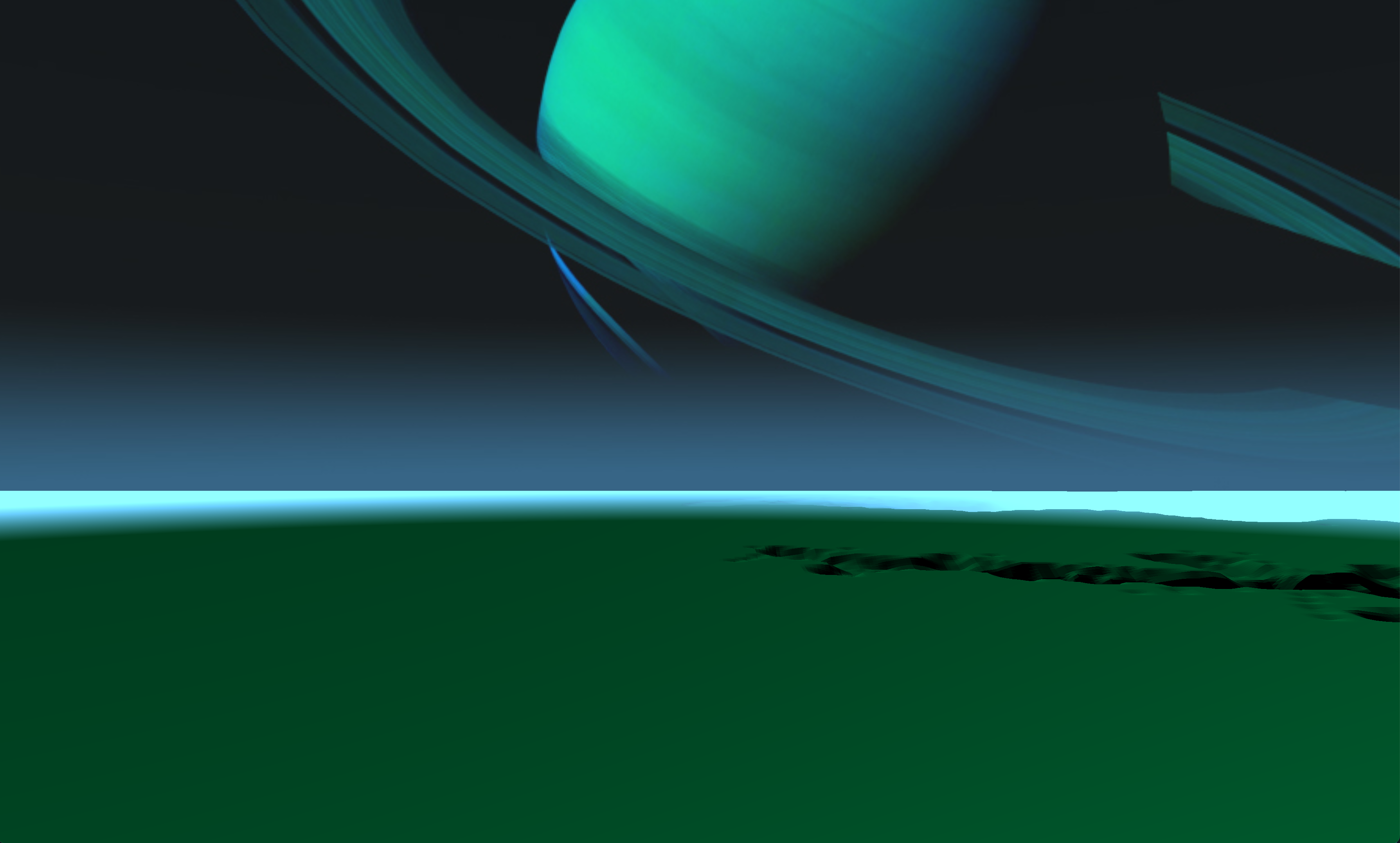
Noise functions are a powerful tool in procedural map generation, providing natural variation, controlled randomness, and procedural variation. The images below depict a comparison of the terrain before and after incorporating noise functions:
 |
 |